High lighter stunt-gun
How To Make A High-Lighter Stun-Gun
The Stun-Gun
In this article, I'll show you how to make a small, weaponized highlighter. Before I get into how to built this device, let me warn you. This device is harmful! When used, it can cause burns and/or serious muscle spasms. The voltage is potentially deadly! DO NOT attempt to build this device unless you are experienced with safety, electronics, soldering, and understand circuit schematics.
Step 1 The Materials
- A Highlighter
- A disposable Kodak camera
- One 300V 10uf-80uf capacitor (can be found at most electronics stores, or online here)
- Rechargeable AA battery
- Miscilanious wire
- A temporary switch (can be found at most electronics stores, taken out of most electronics (make sure they belong to you before you dismantle them), or found online here)
- Two needles (sewing needles work fine)
- Hot glue
- Electrical tape
Step 2 The Tools
- Hot glue gun
- Wire cutters
- Soldering iron
- Solder
- Hot glue gun
- Flux (unless you have flux-core solder)
Step 3 The Procedure
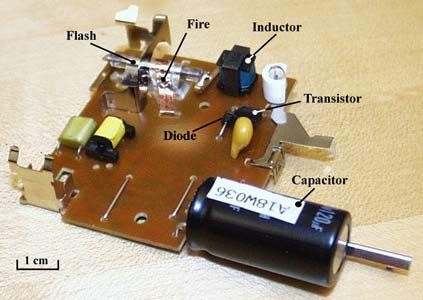
- First, dismantle the disposable camera and discharge the capacitor. Using the photo below, locate the large, black battery-like cilendar, and cross the two prongs with a screw driver. This is for safety purposes, since the capacitor can hold a charge for long periods of time, and electrocute you if you complete the short with your fingers.

2. Dismantle the highlighter. Take out the ink and felt tip and dispose of them.
3. The circuit is quite simple, consisting of the transformer, transistor, resistor, and diode from the camera circuit. Follow these steps to create the circuit, or the schematic below (circuit must be made standalone, with NO protoboard).
Note: If following the instructable guide, replace the film capacitor used with the one from the camera circuit/other (purchased online). Also, If the capacitor from your camera circuit is under 80uf (just look on the side of the capacitor, it should say. If not, don't risk it), you can use it in place of the capacitor on the taser.

Ensure the final circuit is as small as possible. It should look similar to this (the little black battery-like object in the top right corner is the capacitor):

4. To build the switch and battery, take your temporary button and solder two, three inch long wires to the prongs of the switch. Next, melt two holes in the bottom cap of the highlighter. insert the wires, then glue the switch to the outside of the cap (see image below). Solder one switch-wire to the positive side of the battery (see image below, black object in top right. Similar in looks to a capacitor but without the white line). Solder the second switch wire to the positive of the transformer circuit. Cut a one inch piece of wire and solder it from the battery's negative to the transformer circuit's negative.
Note: I used a different type of battery, but AAs work just as well.

5. Cut two, two inch long wires and solder them to the capacitor. Next, locate the diode and ground portion of your circuit (note: The capacitor is already shown on the schematic). Ensure the polarity is correct (the diode connects to the little white line on the capacitor, or negative prong). Now, take the needles mentioned earlier and cut off any "end-nub" part of the needle. Solder the needles to the capacitor like this:
Note the small piece of electrical tape on the end of the capacitor. This is important to prevent shorting, do not forget it.

The layout of the highlighter insertion (in order from bottom to top) should be:
- The switch
- The battery
- The transformer
- The capacitor
- The prongs
It should look something like this when built correctly:

7. Test it, ensure it works properly. When the trigger button is pressed, a high frequency "weeing" should be heard. After a second, short the two prongs with a screw driver, if working properly, there should be a spark. Be careful! Don't shock yourself.
7. Once soldered and tested, carefully insert it into the highlighter case. The capacitor should fit all the way into the top portion of the case, and the needles should stick out of the end about half an inch. Inject hot glue into the top end, and aline the prongs (needles) so that they are in the center of the pen-hole (do all of this before the hot glue dries). Allow the glue to dry, and carefully insert the rest of the circuit. The transformer unit should fit in sideways, like this:

8. Clip in the end cap, and your done! The battery should last a good 2000 charges, so there shouldn't be a need to recharge for a long time. When necessary, just pop off the end cap and charge the battery. To use, pull off the cap, press the button on the bottom, and short the two needles. Before you test it on people, get their permission first, unless they're occupied in attacking you.
Tips
- If you solder it all together and it doesn't work, first check for polarity issues, then your circuit itself.
- Ensure you cut enough wire to make the entire circuit easy to insert, but not too long, otherwise space issues will occur.
- Don't cram!! If it doesn't fit, take it out and change the length of the wire.
Warnings
- I am not responsible for any harm you cause yourself or other living beings while using this device.
- Soldering irons are hot! Be careful, don't burn yourself
- Same goes for the glue gun
- When de-soldering the transistor from the camera circuit, don't overheat it! Be quick, but careful
